My innovative design was to make a small, stackable board using low-cost, low-power microcontrollers with 10-bit ADC that provide a (theoretical) 5mV per cell resolution.
When I originally conceived these things, they were "distributed" - each of the
boards was fitted by a group of cells. Partly because it
was an embryonic idea and I "thought" they would only be there temporarily
while I worked out what was going on with my own system at the time!
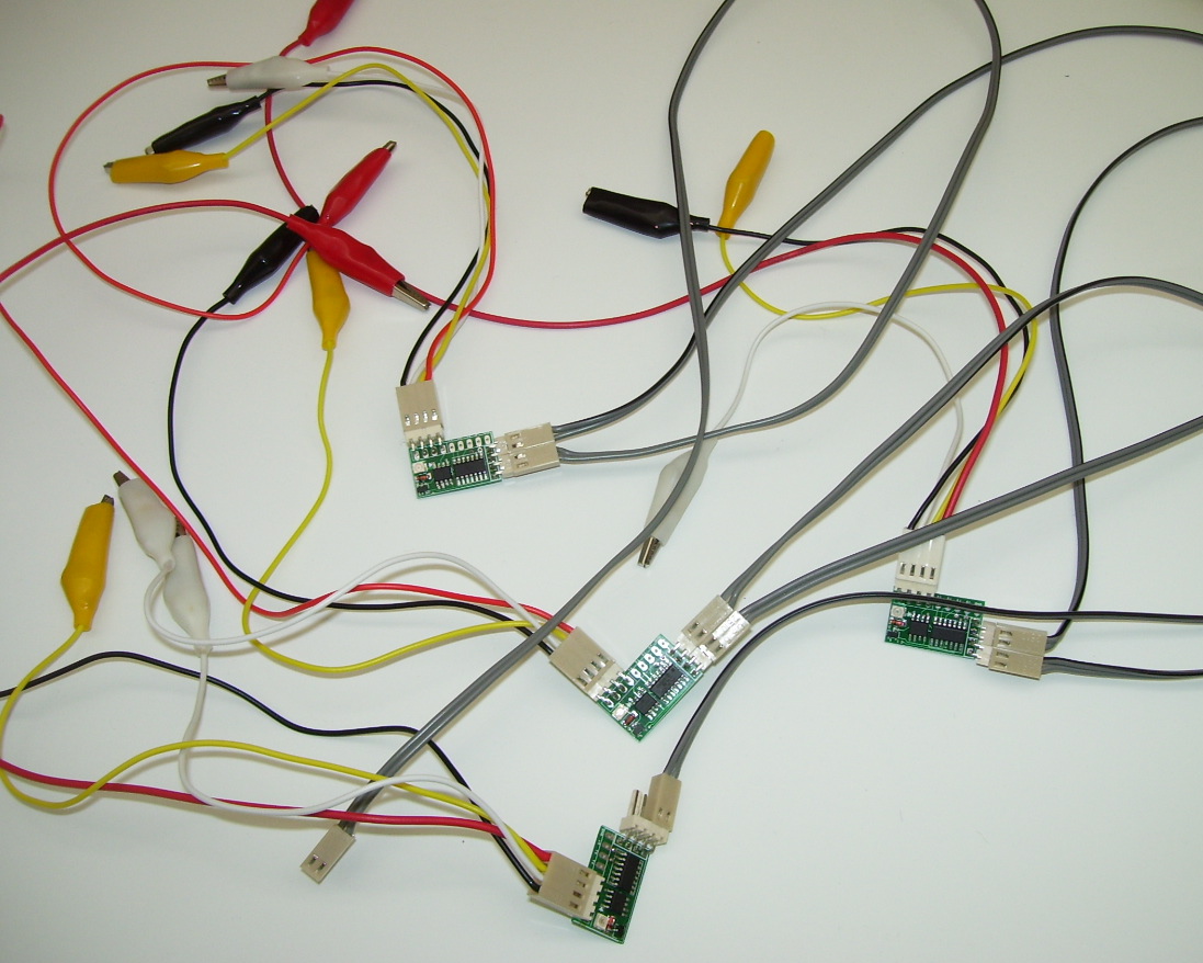
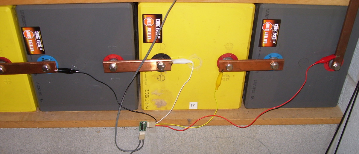
Inputs were just temporarily connected to the cells with crocodile clips.
Little did I know at the time, it would be SO useful it would become a permanent fixture.
When the first of the guys in IRC started ordering them, they asked if it was possible to leave them all together in a single assembly... of course it was.
Typical wiring for 12-cell (24V) battery:

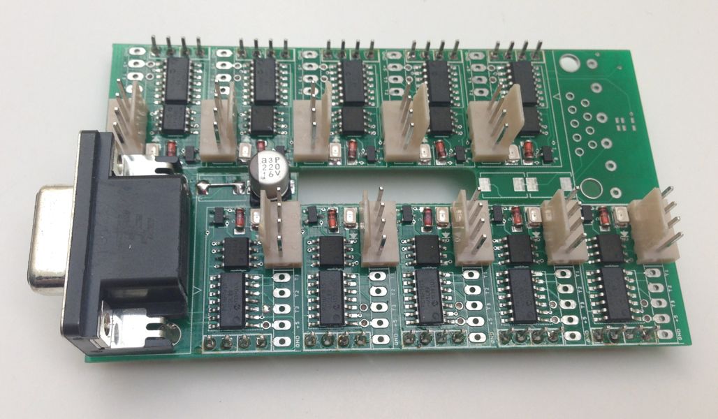
Although shown as seperate boards with linking wires, most people have them assembled as a single unit with an interconnect jumper, like this.
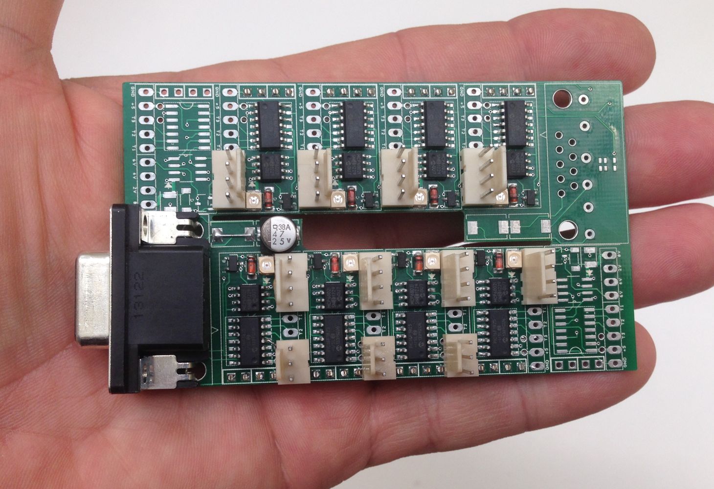
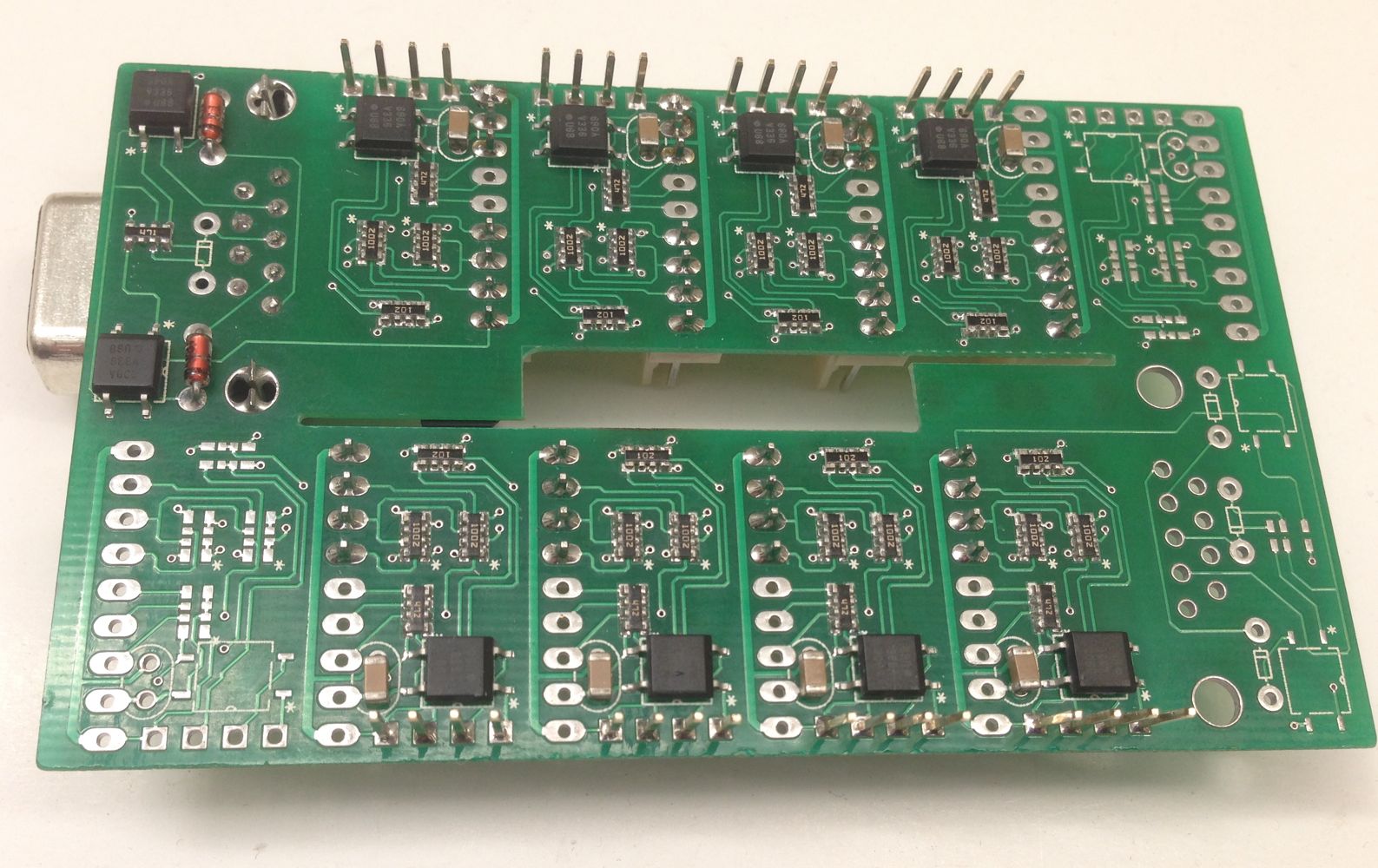
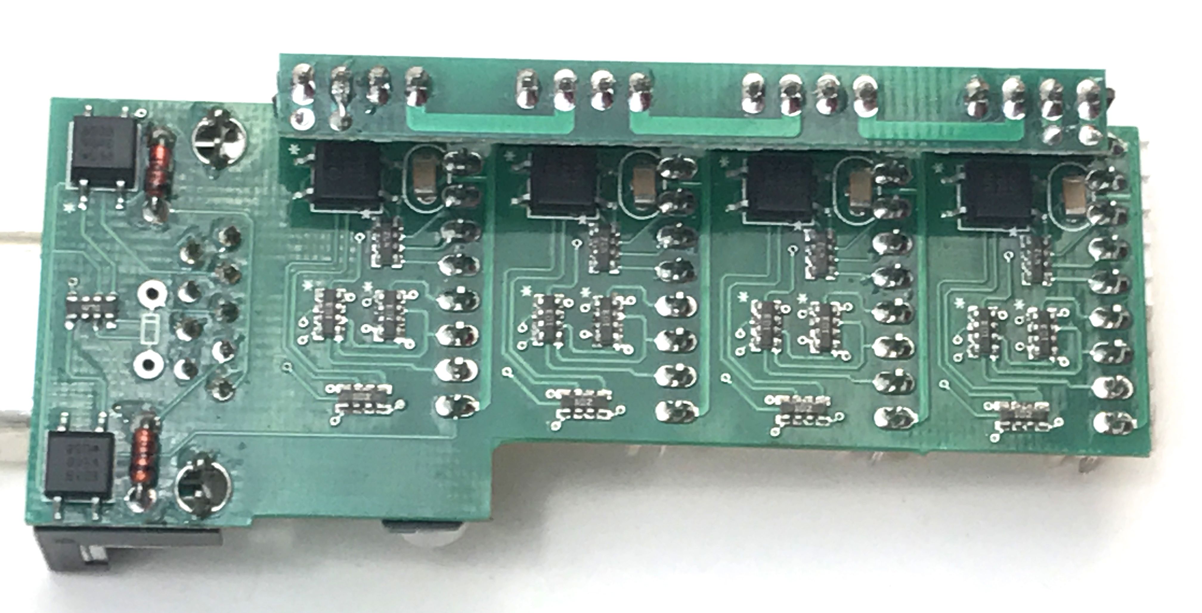
Typical 48V monitor with 24 x 2V cells, (8 "boards") (top and bottom views)
Not mentioned until now, is that each board can take up to three DS18B20 temperature sensors. This is sufficient to monitor the voltage and temperature of each individual cell in the bank. Of course, temperature monitoring is optional. You can choose to monitor one cell in a group, or a couple of points in the entire battery, or to use sensors for ambient monitoring, etc. One enterprising user reported they used temperature sensors on the inter-connect bus bar to narrow down the proper bus bar size over time and to help diagnose interconnect connection problems.
For more cells, up to 30 cells can be monitored on one board and boards can be cascaded. The highest voltage system I've done to date is 60-cells (120V) although the system should theoretically work up to 255.999 volts. Each stage is optically isolated.
Output from the device is 4800 baud serial (RS232), plain ASCII text. Typical output looks like this:
V01 3.362
T01 27.3
V02 3.381
T02 27.1
V03 3.338
T03 26.8
V04 3.324
V05 3.351
V06 3.331
V07 3.356
V08 3.364
V09 3.364
V10 3.376
V11 3.385
V12 3.373
V13 3.375
V14 3.381
V15 3.384
V16 3.377
Y15 53.842 16 3.365 3.465 3.265
This is from an active LiFePO4 (LFP) bank with nominal voltage of 53V.
Technical stuff for geeks.
The boards use a proprietry synchronisation system so they all sample their cells
at as close to the same time as is possible. This is important on active batteries, as instantaneous
current through the cells will alter the voltage. In order to reasonably compare cells, they should be sampled
as close to simultaneously as possible.
The boards sample each cell 16 times for each reading in order to minimise any jitter due to noise.
My monitors have no variable resistors. The design uses level-shifting to ensure maximum ADC resolution
is available for every cell, without loss of precision due to voltage division.
Resistors are in arrays where drift due to age and temperature should be similar. The
design does not rely on the absolute resistance, but the ratio of the resistors, so any drift effectively cancels out.
Each monitor is calibrated at manufacture. The calibration factors are stored in non-volatile memory.
While not usually necessary, they can be recalibrated in the field if required.
The basic circuit is here.